
The chip manufacturing process is inherently prone to defects, commonly referred to as faults. Detecting these faults requires a structured approach. A fault is considered testable if a well-defined procedure exists to expose it in the actual silicon. To detect as many faults as possible in a design, additional logic must be integrated into the circuit. This methodology, known as Design for Testability (DFT), encompasses various techniques that make testing feasible. In this blog, we will explore one of the most widely used DFT techniques for logic testing: Scan and Automatic Test Pattern Generation (ATPG). But first, let’s understand the concept of fault models.
Fault Models: Simplifying Fault Detection
Fault models abstract the behavior of manufacturing defects, enabling the generation of test vectors to detect them. These include:
- Functional Defects: Represented by the Stuck-at Fault Model.
- Current Defects: Represented by the Pseudo Stuck-at Fault Model (IDDQ).
- Speed Defects: Represented by the At-speed Fault Model and Path Delay Fault Model.
For simplicity, this blog focuses on the two most common fault models: stuck-at and at-speed fault models.
1. Stuck-at Faults
The stuck-at fault model is the most prevalent in the industry. It represents defects where a circuit node is permanently connected to either the power supply (stuck-at-1 fault) or ground (stuck-at-0 fault). These faults can occur at the input or output of a gate. For example, a 2-input AND gate can have six possible stuck-at faults.
In a simple circuit, detecting a stuck-at-0 fault at the output of an AND gate may require specific input patterns. While identifying these patterns in small circuits is feasible, larger circuits rely on ATPG tools. These tools generate patterns to test all possible fault locations using advanced algorithms. If certain faults cannot be tested, they are classified as untestable.
2. At-speed Faults
At-speed faults model defects that cause delays at gate input-output ports. These delays are tested for logic transitions: slow-to-rise (0-to-1) or slow-to-fall (1-to-0). Similar to stuck-at faults, each port in a circuit can have multiple at-speed faults. For instance, a slow-to-fall fault at an AND gate’s output can alter the values captured by subsequent flip-flops, depending on the input state. ATPG tools generate patterns to detect these faults as well.
Scan and ATPG: Simplifying Fault Detection
Scan is a design modification technique aimed at increasing a circuit’s testability. ATPG (Automatic Test Pattern Generation) generates the required test patterns. Together, they streamline the detection of stuck-at and at-speed faults.
Pre-scan vs. Post-scan Circuits
Testing faults in sequential circuits without scan insertion is challenging. It’s difficult to control the state of flip-flops via primary inputs and observe the captured responses. ‘Scan Insertion’ addresses this by converting a sequential circuit into a pseudo-combinational circuit during testing.
Steps in Scan Insertion
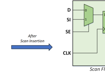
- Converting Regular Flip-Flops to Scan Flip-Flops All flip-flops are converted into scan flip-flops except:
- Flip-flops explicitly excluded by the user (non-scan flip-flops).
- Flip-flops with Design Rule Check (DRC) violations.
- Stitching Scan Flip-Flops into Scan Chains The scan flip-flops are connected to form scan chains. The number of chains depends on factors such as:
- Chain length.
- Clock domain mixing.
- Power and voltage domain considerations.
Testing with Scan Chains
During testing:
- To initialize flip-flops, the scan enable (SE) signal is set to 1, enabling a serial data path. Values are shifted in through a primary input called Scan-Input.
- To capture responses, SE is set to 0, and the captured data is shifted out via Scan-Output.
This configuration makes the scan flip-flop’s output act as a pseudo-primary output and its input act as a pseudo-primary input, effectively creating a combinational circuit for testing purposes.
Role of ATPG in Scan Testing
Once scan chains are set up, ATPG tools generate patterns and their expected responses in pre-silicon testing. These patterns are stored in the memory of Automatic Test Equipment (ATE). During post-silicon testing, the ATE loads the patterns into the chip and compares the actual responses with the expected results, determining a pass or fail status.
Conclusion
DFT techniques like Scan and ATPG play a crucial role in ensuring the reliability of integrated circuits. By abstracting faults, generating test patterns, and utilizing scan chains, these methodologies simplify the testing of complex designs, ensuring high-quality chip manufacturing. With ongoing advancements in DFT, the future holds even more robust solutions for fault detection and circuit validation.